


Connecting a laser module to an Arduino opens up a world of possibilities for makers, hobbyists, and educators. These compact, low-power modules are commonly used in applications like laser engraving, distance sensing, alignment tools, and light shows. This guide walks through the fundamentals of wiring, programming, and safely operating a laser module with an Arduino board.
Most laser modules available for DIY use operate at 5V, making them compatible with the Arduino’s voltage output. A typical red dot laser module has three pins: VCC (power), GND (ground), and SIG (signal). To connect it, link the VCC pin to the Arduino’s 5V pin, GND to any GND pin, and SIG to a digital pin—for example, pin 9. Some modules include built-in resistors, but if yours doesn’t, add a current-limiting resistor (e.g., 220Ω) in series with the SIG pin to protect the laser diode from overcurrent.
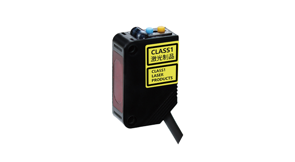
Safety is paramount when working with lasers. Even low-power modules can cause eye injury. Always wear appropriate laser safety goggles, avoid pointing the beam at people or reflective surfaces, and check local regulations regarding laser use. For projects requiring higher power, consider using enclosures or interlocks.
Programming the Arduino to control the laser is straightforward. Using the digitalWrite() function, you can turn the laser on or off. For instance, setting the signal pin to HIGH activates the laser, while LOW deactivates it. Here’s a basic example:
``cpp
int laserPin = 9;
void setup() {
pinMode(laserPin, OUTPUT);
}
void loop() {
digitalWrite(laserPin, HIGH); // Laser ON
delay(1000);
digitalWrite(laserPin, LOW); // Laser OFF
delay(1000);
}
``
This simple blink sketch can be expanded for more complex behaviors, such as pulsing the laser with PWM (Pulse Width Modulation) for brightness control. By using analogWrite() on a PWM-capable pin, you can adjust the intensity.
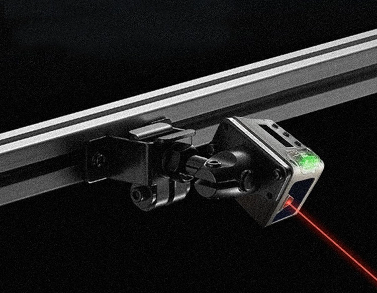
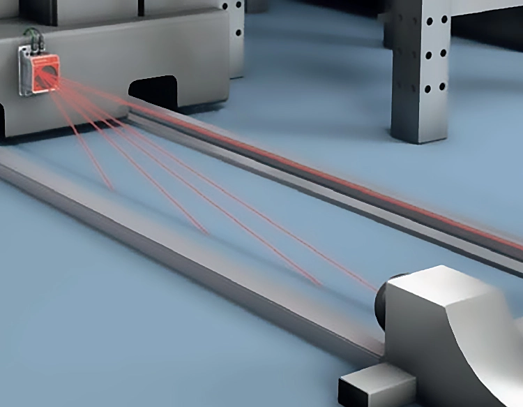
Practical applications are diverse. In engraving setups, the laser can be controlled via G-code from software like Grbl, turning the Arduino into a CNC controller. For sensing, pairing the laser with a photoresistor or photodiode allows for tripwires or distance measurement through triangulation. In artistic installations, multiple lasers can be synchronized with music or motion sensors using additional components like shift registers or motor drivers.
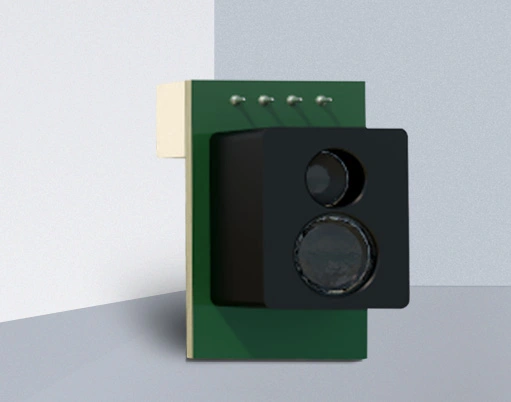
When selecting a laser module, consider wavelength (common red lasers are around 650nm), power output (typically 5mW for beginner-safe modules), and modulation capability. Modules with TTL (Transistor-Transistor Logic) support enable precise digital control, which is useful for data transmission or complex patterns.
Troubleshooting common issues involves checking connections with a multimeter, ensuring the Arduino is properly powered, and verifying code uploads. If the laser doesn’t turn on, test the module directly with 5V and GND to rule out wiring problems. Remember that continuous operation may generate heat; adding a small heatsink can prolong the module’s lifespan.
Integrating a laser module with Arduino encourages experimentation while teaching core electronics and coding concepts. Start with simple on/off control, then explore libraries or external hardware like stepper motors to create dynamic projects. Always document your work and share findings with the maker community to foster innovation and safe practices.