


Connecting a laser sensor to an Arduino opens up a world of possibilities for precise distance measurement, object detection, and automation projects. Unlike common infrared (IR) or ultrasonic sensors, laser-based modules offer significantly higher accuracy and a longer range, making them ideal for applications like robotics, security systems, and industrial monitoring. This guide will walk you through the fundamentals, from selecting the right laser sensor to writing the Arduino code and testing your setup.
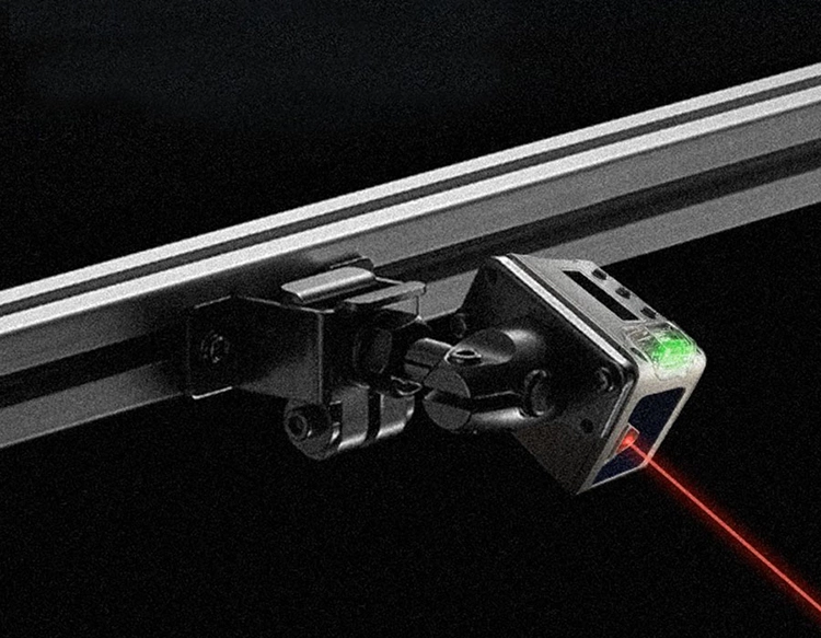
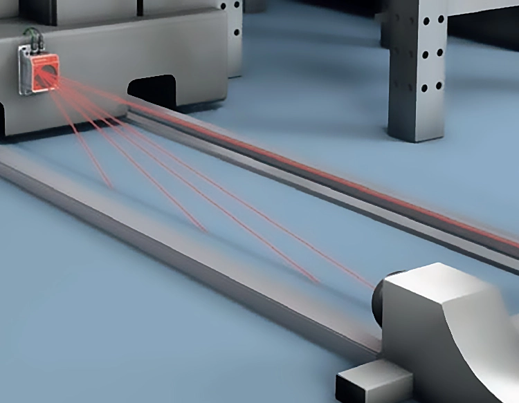
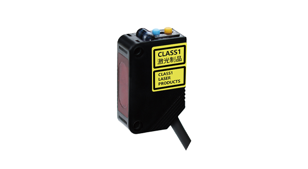
First, it's crucial to understand the type of laser sensor suitable for Arduino. For hobbyists and educational projects, a Time-of-Flight (ToF) laser sensor, such as the VL53L0X or VL53L1X, is highly recommended. These sensors are compact, eye-safe (Class 1 laser), and communicate via the I2C protocol, which requires only two pins on the Arduino. They can measure distances from a few centimeters up to several meters with millimeter-level precision. Another popular option is a laser tripwire module, which consists of a separate laser emitter and a receiver; it detects when an object breaks the beam. For this tutorial, we will focus on the VL53L0X ToF sensor due to its ease of use and reliability.
To get started, you will need an Arduino board (Uno or Nano are excellent choices), a VL53L0X sensor, a breadboard, and jumper wires. Begin by connecting the sensor to the Arduino. The VL53L0X has four primary pins: VIN, GND, SDA, and SCL. Connect VIN to the Arduino's 5V pin, GND to GND, SDA to the A4 pin (or the dedicated SDA pin on boards like the Nano), and SCL to the A5 pin (or the SCL pin). Double-check the connections to avoid any short circuits.
Next, you need to install the necessary library in the Arduino IDE. Open the IDE, go to Sketch > Include Library > Manage Libraries. In the Library Manager, search for "VL53L0X" and install the library by Pololu. This library provides simple functions to initialize the sensor and read distance values. Once installed, you can upload a basic test sketch. Here is a simple example:
``cpp
#include
#include
VL53L0X sensor;
void setup() {
Serial.begin(9600);
Wire.begin();
sensor.init();
sensor.setTimeout(500);
}
void loop() {
int distance = sensor.readRangeSingleMillimeters();
if (sensor.timeoutOccurred()) {
Serial.println("Sensor timeout!");
} else {
Serial.print("Distance: ");
Serial.print(distance);
Serial.println(" mm");
}
delay(100);
}
`
This code initializes the sensor and continuously prints the measured distance in millimeters to the Serial Monitor. Open the Serial Monitor (Tools > Serial Monitor) at a baud rate of 9600 to see the readings. Try placing an object at different distances from the sensor to observe how the values change. The sensor performs best with non-reflective, solid objects in well-lit environments, though it can also operate in low light.
For more advanced applications, such as object detection, you can modify the code to trigger an action when an object is within a specific range. For instance, you can activate a buzzer or an LED when something comes closer than 200 mm. Add an LED connected to pin 13 with a current-limiting resistor, and update the loop function:
`cpp
void loop() {
int distance = sensor.readRangeSingleMillimeters();
if (distance > 0 && distance< 200) {
digitalWrite(13, HIGH); // Turn on LED
Serial.println("Object detected!");
} else {
digitalWrite(13, LOW); // Turn off LED
}
delay(50);
}
``
This creates a simple proximity alarm. You can expand this concept to build a laser security system, a robot that avoids obstacles, or a precise height measurement tool. When designing enclosures, ensure the laser sensor is mounted securely and aligned properly, as even slight angles can affect accuracy. Avoid pointing the sensor directly at reflective surfaces like glass or mirrors, as this may cause erroneous readings.
Troubleshooting common issues is part of the process. If the sensor fails to return values, verify the I2C connections and ensure the library is correctly installed. Sometimes, multiple I2C devices can conflict; each must have a unique address. The VL53L0X library allows changing the sensor's I2C address programmatically if needed. Power supply noise can also interfere; adding a 100µF capacitor near the sensor's VIN and GND pins can stabilize the voltage.
In summary, integrating a laser sensor with Arduino is a straightforward process that yields professional-grade results. The key steps involve selecting a compatible sensor like the VL53L0X, wiring it correctly, installing the dedicated library, and writing code to read data. With this foundation, you can develop intricate projects that require accurate spatial awareness. Experiment with different sensors and code modifications to explore the full potential of laser technology in your Arduino creations.