


The MV100-RT/35/95/103 photoelectric switch represents a critical component in modern industrial automation and control systems. As a type of through-beam sensor, this device operates by transmitting a light beam from an emitter to a receiver. When an object interrupts this beam, the switch triggers a signal, enabling precise detection, counting, or positioning tasks. The specific model designation "MV100-RT/35/95/103" typically encodes key technical specifications. The "RT" often indicates a retro-reflective type, designed to work with a reflector. The numbers "35/95/103" commonly refer to operational parameters such as sensing distance (potentially up to 10 meters), housing dimensions, or specific electrical characteristics like voltage input range (e.g., 10-30V DC) and output configuration (e.g., NPN or PNP transistor output).
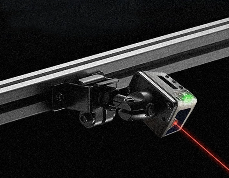
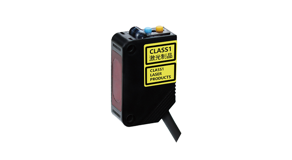
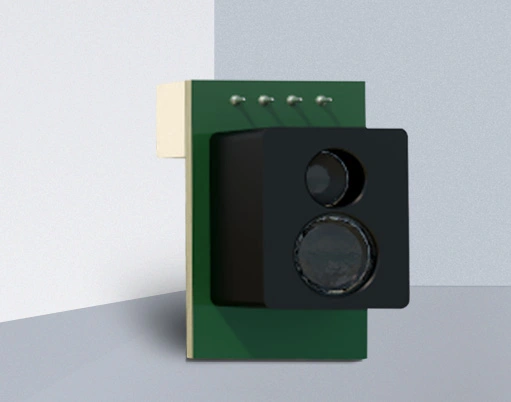
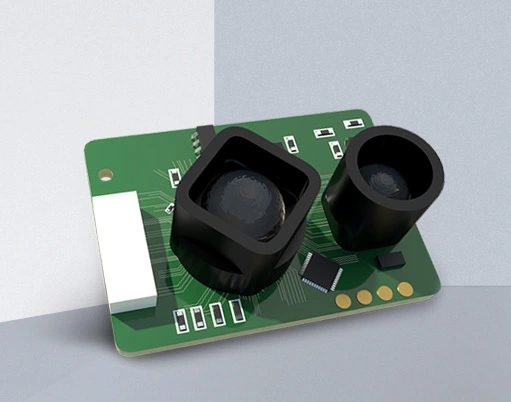
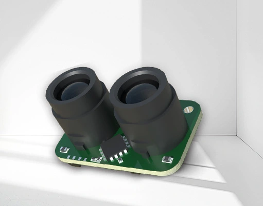
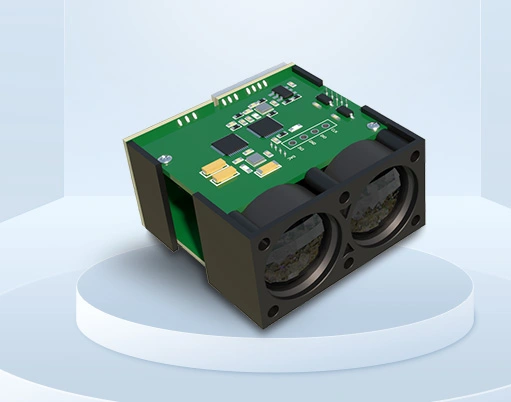
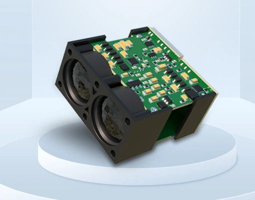
Constructed for durability in harsh industrial environments, the MV100-RT/35/95/103 usually features a robust housing made from materials like nickel-plated brass or stainless steel, offering high resistance to dust, moisture, and mechanical impact. Its ingress protection rating is typically IP67, ensuring reliable operation even in challenging conditions involving coolants or washdowns. The core technology involves an infrared LED light source and a synchronized receiver. In retro-reflective mode, the emitter and receiver are housed in the same unit. The emitted light beam travels to a specialized reflector and bounces back to the receiver. An object passing between the sensor and the reflector breaks this beam, causing the output state to change. This design allows for easier installation and alignment compared to through-beam models requiring separate emitter and receiver units.
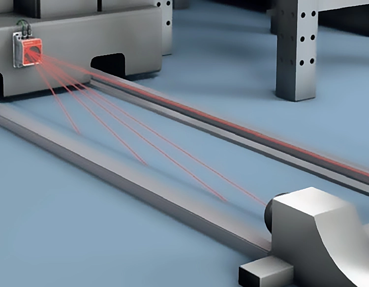
A primary application for the MV100-RT/35/95/103 is on production lines for object detection. It can reliably detect the presence, absence, or passage of items on conveyor belts, whether they are boxes, bottles, or machine parts. Its high switching frequency and fast response time make it suitable for high-speed counting and sorting operations. In packaging machinery, it ensures correct product positioning before sealing or labeling. Within automated assembly systems, it verifies the correct placement of components. Another significant use is in safety systems, where it can act as a safety light curtain or part of an access control mechanism to protect personnel from moving machinery. It is also employed in material handling for level detection in silos or for monitoring door positions.
Selecting the correct photoelectric switch requires careful consideration of several factors. The sensing distance must be appropriate for the application, with a sufficient margin to account for potential misalignment or environmental factors. The size and material of the target object influence the choice; smaller or transparent objects may require a sensor with a focused beam or special sensitivity adjustments. The environmental conditions are paramount. Factors like ambient light, dust, fog, or temperature extremes can affect performance. The MV100-RT/35/95/103 is generally designed to compensate for background light interference. The required output type must match the control system's input card—whether it's a sinking (NPN) or sourcing (PNP) transistor output. Additionally, connection type (pre-wired cable or quick-disconnect) and housing shape (cylindrical or rectangular) are chosen based on mounting constraints.
Proper installation and alignment are crucial for optimal performance. For retro-reflective sensors like the MV100-RT/35/95/103, the unit must be precisely aligned with its reflector. Many models feature a visible red LED or a green alignment indicator to simplify this process. The sensor should be mounted securely to prevent vibration from causing misalignment. It is essential to ensure the target object passes through the detection zone effectively. Regular maintenance involves keeping the lens clean from dirt, oil, or debris that could attenuate the light signal. Periodically checking the alignment and the condition of the reflector is also recommended. Understanding the status indicators (power, output, stability) helps in quick troubleshooting. Common issues include failure to detect due to misalignment, dirty lenses, or incorrect electrical connections.
When integrating the MV100-RT/35/95/103, engineers must follow standard electrical safety practices. The power supply should be stable and within the specified voltage range. Output loads must not exceed the sensor's maximum current rating to prevent damage. For installations in explosive atmospheres, intrinsically safe versions may be required. Always consult the manufacturer's official datasheet for the exact specifications, wiring diagrams, and safety instructions pertaining to the specific MV100-RT/35/95/103 model in use. Adherence to these guidelines ensures long-term reliability, reduces downtime, and maintains the efficiency of the automated process. The versatility and robustness of this photoelectric switch make it a fundamental building block for creating responsive and intelligent industrial systems.