


Photoelectric switches are fundamental components in modern industrial automation, sensing, and control systems. Among the diverse models available, the LD39, LV39, 30, 40a, 116, and 126a series represent specific types with distinct characteristics and applications. This guide provides a detailed, factual overview of these photoelectric switches, explaining their operation, key differences, and typical use cases without promotional bias.
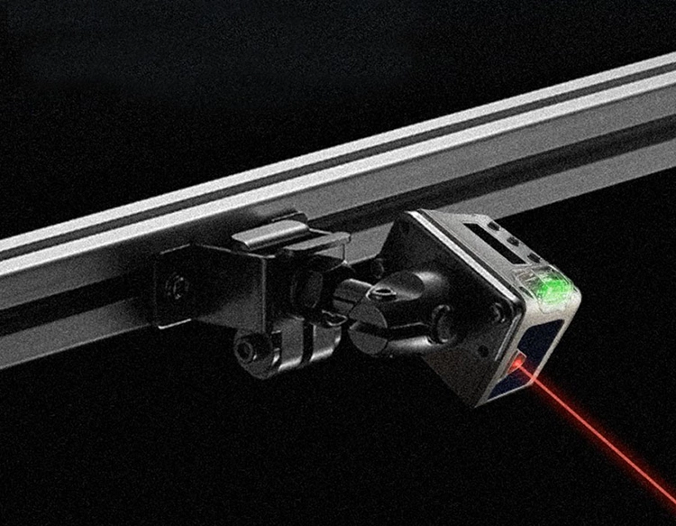
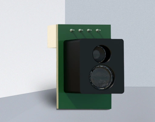
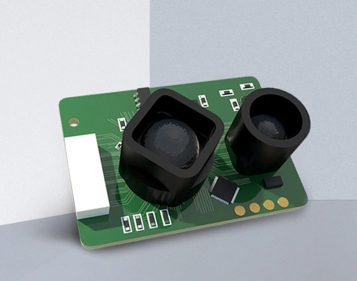
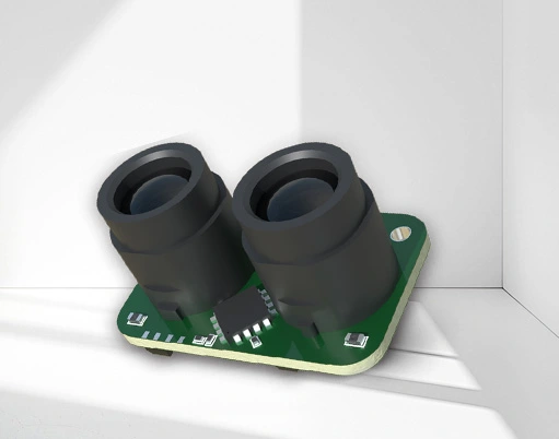
At its core, a photoelectric switch operates by emitting a beam of light (visible, infrared, or laser) from a transmitter and detecting it with a receiver. An object's presence or absence is determined by how it interacts with this light beam. The primary sensing modes are through-beam, retro-reflective, and diffuse-reflective. Through-beam models have separate emitter and receiver units, offering the longest sensing ranges and highest reliability. Retro-reflective types use a single housing with both emitter and receiver, relying on a reflector to bounce the light back; they are interrupted by the target object. Diffuse-reflective sensors also have a single housing but detect light reflected directly off the target object itself, making them simpler to install but with shorter ranges and potential sensitivity to object color and surface finish.
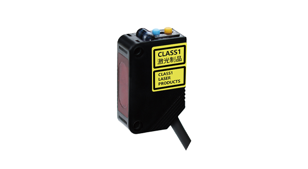
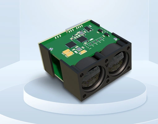
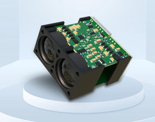
The designations like LD39, LV39, 30, 40a, 116, and 126a typically refer to specific housing styles, form factors, or performance specifications from various manufacturers. For instance, the "39" series often indicates a compact, rectangular housing. The "30" and "40" may denote cylindrical barrel-style sensors with different diameters (e.g., 30mm or 40mm). The suffixes "a", "116", and "126a" could specify variations in output type (e.g., NPN or PNP transistor, relay), sensing range, connection method (e.g., cable or connector), or special features like background suppression. It is crucial to consult the specific manufacturer's datasheet for exact specifications, as these codes are not universally standardized across all brands.
Key technical parameters define a photoelectric switch's suitability for an application. Sensing range is the maximum reliable distance at which the sensor can detect a standard target. The LD39 or LV39 models might offer a range suitable for medium-distance detection on conveyor lines. Response time indicates how quickly the sensor's output changes state after detection, critical for high-speed counting or sorting. Light sources vary; infrared is common for immunity to ambient light, while laser sources provide precise, long-range spotting for alignment tasks. Environmental ratings, such as IP67 (Ingress Protection), signify resistance to dust and water immersion, which is vital for harsh industrial environments. Output configuration is another critical factor, with common types being DC 3-wire (NPN sinking or PNP sourcing) for PLC integration, or relay outputs for directly switching higher-power loads.
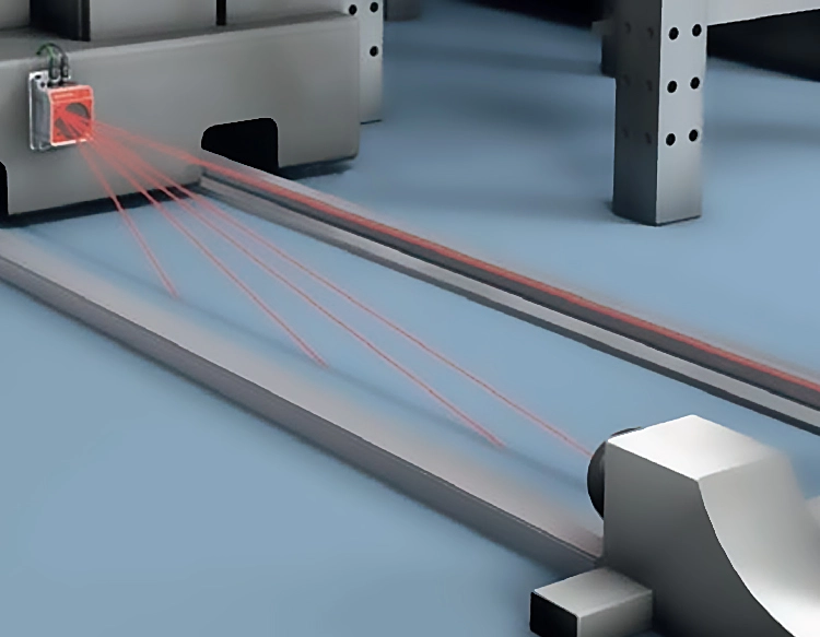
In practical applications, these sensors perform reliably across numerous industries. In material handling and packaging, a 30-series diffuse sensor might detect the presence of boxes on a conveyor belt, triggering a downstream process. The more robust 40a or 116 models, with higher environmental ratings, could be used in automotive assembly plants to sense parts in wash-down areas. In the electronics industry, precise LV39 through-beam sensors are often employed for accurate counting of small components or verifying the presence of circuit boards. Logistics and warehouse automation heavily utilize retro-reflective models like the 126a for pallet detection, gate control, and ensuring clear pathways for automated guided vehicles (AGVs). Their non-contact nature prevents product damage and reduces mechanical wear compared to limit switches.
Selecting the correct photoelectric switch requires a systematic analysis of the application needs. First, identify the object properties: size, material, color, and surface texture. A shiny metallic object may require a polarized retro-reflective or background suppression diffuse sensor to avoid false triggers. Second, consider the installation environment, including temperature extremes, exposure to chemicals, vibration, and ambient light conditions. Third, define the required sensing distance and mounting constraints. Finally, determine the necessary electrical interface to match the control system's input requirements. Proper alignment and installation are paramount; even the best sensor will fail if misaligned. Regular maintenance, such as cleaning the lens from dust or debris, ensures long-term, stable operation.
Understanding the nuances between models like the LD39, LV39, 30, 40a, 116, and 126a allows engineers and technicians to make informed decisions. These components are not interchangeable simply by size; electrical compatibility, sensing technology, and environmental robustness must align with the task. By focusing on the fundamental operating principles and specific technical data, users can effectively integrate these reliable sensors to enhance automation efficiency, improve safety systems, and enable precise control in countless industrial and commercial settings. Their role in enabling automated, efficient, and repeatable processes remains indispensable.