


In the realm of industrial automation, precision, reliability, and durability are non-negotiable. Sensors form the critical interface between the physical world and control systems, and among them, photoelectric switches stand out for their versatility and accuracy. The OBE500-R3F-E2-0,2M-V31 photoelectric switch represents a sophisticated solution designed for demanding applications. This article delves into the technical specifications, operational principles, and practical uses of this specific device, providing a clear understanding of its role in modern automation.
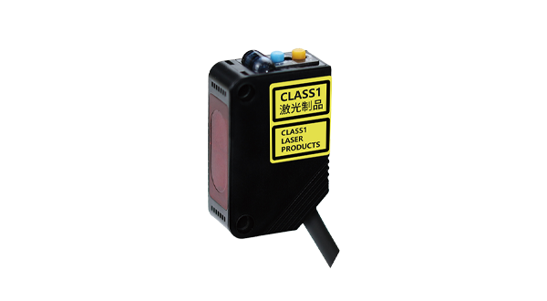
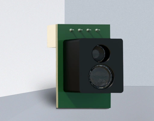
The OBE500-R3F-E2-0,2M-V31 is a retro-reflective photoelectric sensor. This model designation provides key information about its configuration. The "OBE500" typically indicates the series or housing type, often associated with a robust, cylindrical metal or plastic body designed for industrial environments. The "R3F" specifies the sensing mode as retro-reflective with a polarized filter. This is a crucial feature. A standard retro-reflective sensor uses a reflector to bounce light back to the receiver. However, it can be fooled by shiny objects that also reflect light. The polarized filter in the R3F version mitigates this. The sensor emits polarized light. The specialized reflector twists this polarization before sending it back. The receiver only accepts light with this twisted polarization, effectively ignoring direct reflections from glossy surfaces like metal or plastic, thereby ensuring detection reliability.
The "E2" component often relates to the output type. In this context, it commonly signifies a solid-state PNP (sourcing) output. A PNP output switches the positive voltage to the load when an object is detected, which is a standard configuration compatible with many programmable logic controllers (PLCs) and input modules. The "0,2M" clearly denotes a 0.2-meter (200mm) fixed sensing range. This is a moderate range suitable for applications where objects pass within a predictable and relatively close distance to the sensor face. Finally, "V31" usually refers to the electrical connection style, most frequently a pre-wired cable or a specific connector type, such as a 3-pin M12 connector, which is industry-standard for easy installation and maintenance.
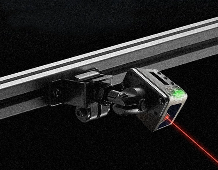
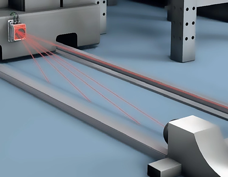
The core operation of the OBE500-R3F-E2-0,2M-V31 is based on light modulation. An internal light-emitting diode (LED), typically infrared or visible red, projects a beam towards a dedicated retro-reflector. This reflector is covered in a material comprising numerous tiny corner cubes that return the light directly to its source. The sensor's receiver monitors the intensity of the returning light. When an opaque object interrupts the beam between the sensor and the reflector, the light signal to the receiver drops, causing the sensor's output to change state (e.g., from OFF to ON). The polarized optics ensure that only light from the genuine reflector, and not stray reflections, triggers the receiver.
This specific combination of features makes the OBE500-R3F-E2-0,2M-V31 exceptionally suited for several industrial scenarios. Its primary application is object detection in material handling and packaging. It can reliably detect the presence or absence of boxes, bottles, or products on a conveyor belt, even if they have shiny labels or metallic packaging, thanks to the polarized filter. It is also ideal for palletizing and depalletizing systems, ensuring layers or individual items are correctly positioned. In automated assembly lines, it can verify if a component has been picked and placed or if a part is in the correct orientation before a robotic operation. Other common uses include detecting the open/closed status of doors or guards on machinery, monitoring fill levels in non-transparent containers by detecting the presence of material at a certain height, and counting objects passing a specific point.
When installing the OBE500-R3F-E2-0,2M-V31, several best practices ensure optimal performance. First, the sensor and reflector must be aligned correctly. Even with a forgiving retro-reflective design, precise alignment maximizes the effective sensing range and signal strength. The environment should be considered; while the sensor is built for industrial settings, excessive dust, steam, or heavy spray can attenuate the light beam. In such cases, choosing a model with a higher IP (Ingress Protection) rating might be necessary, though the OBE500 series typically offers good resistance. The electrical connections must be made according to the datasheet, ensuring the correct voltage (commonly 10-30V DC for such models) is supplied and the load (e.g., a PLC input) is correctly connected to the PNP output wire. Regular maintenance involves keeping the lens and reflector clean from dirt and grime to prevent false triggers or missed detections.
In summary, the OBE500-R3F-E2-0,2M-V31 photoelectric switch is a specialized component engineered for reliable detection in challenging conditions. Its polarized retro-reflective design solves common problems associated with shiny objects, its fixed 0.2-meter range offers stability for mid-range applications, and its standard PNP output ensures easy integration into control systems. For engineers and technicians designing or maintaining automated systems involving conveyor belts, packaging machinery, or assembly stations, understanding the capabilities of this sensor is key to implementing a robust and fault-resistant detection solution. Its design underscores a commitment to operational certainty in fast-paced industrial environments where sensor failure can lead to costly downtime.